Pneumatic Platform
Automated surgical support system integrating an intelligent soft robotics surface and a smart robotic arm.
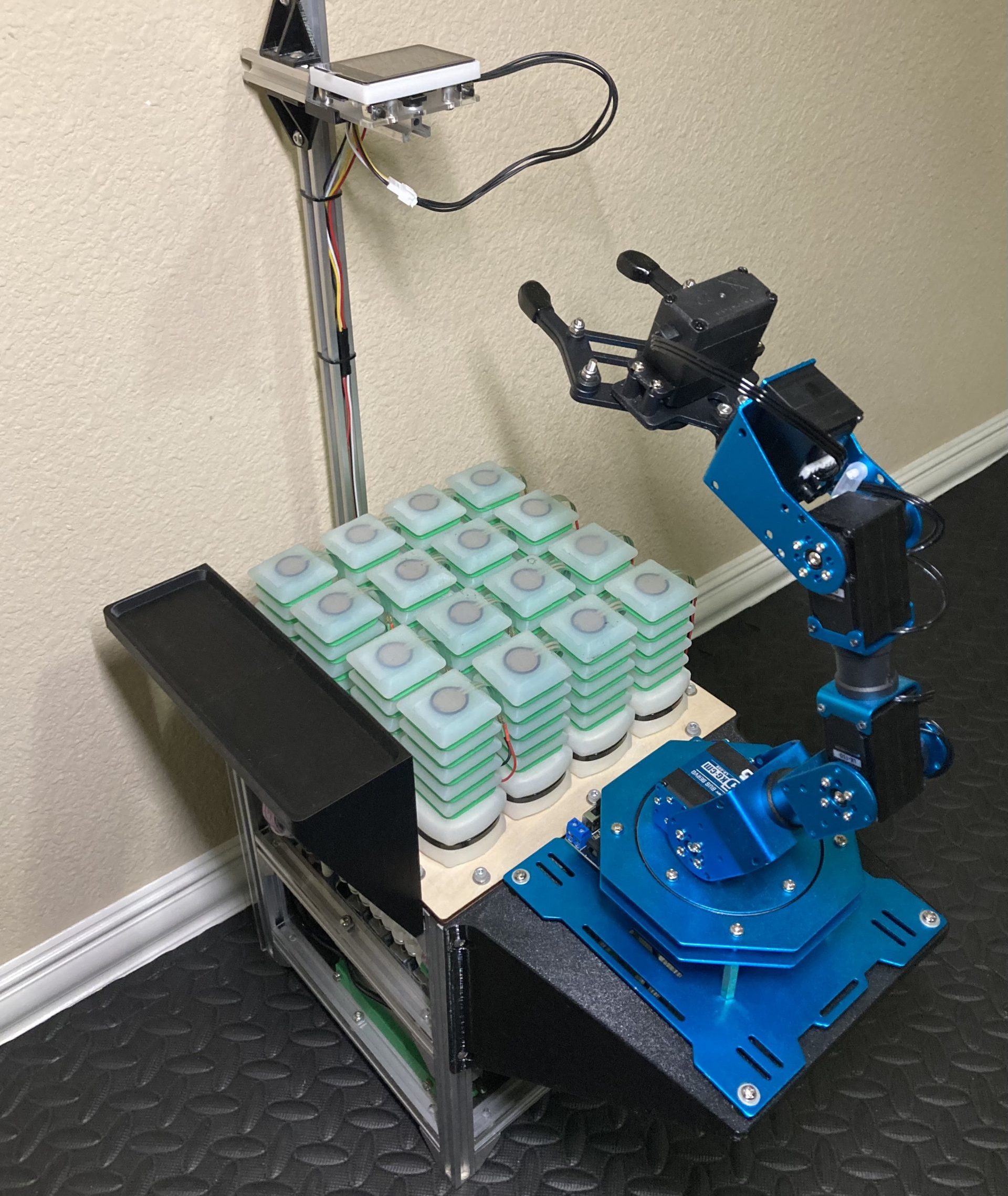
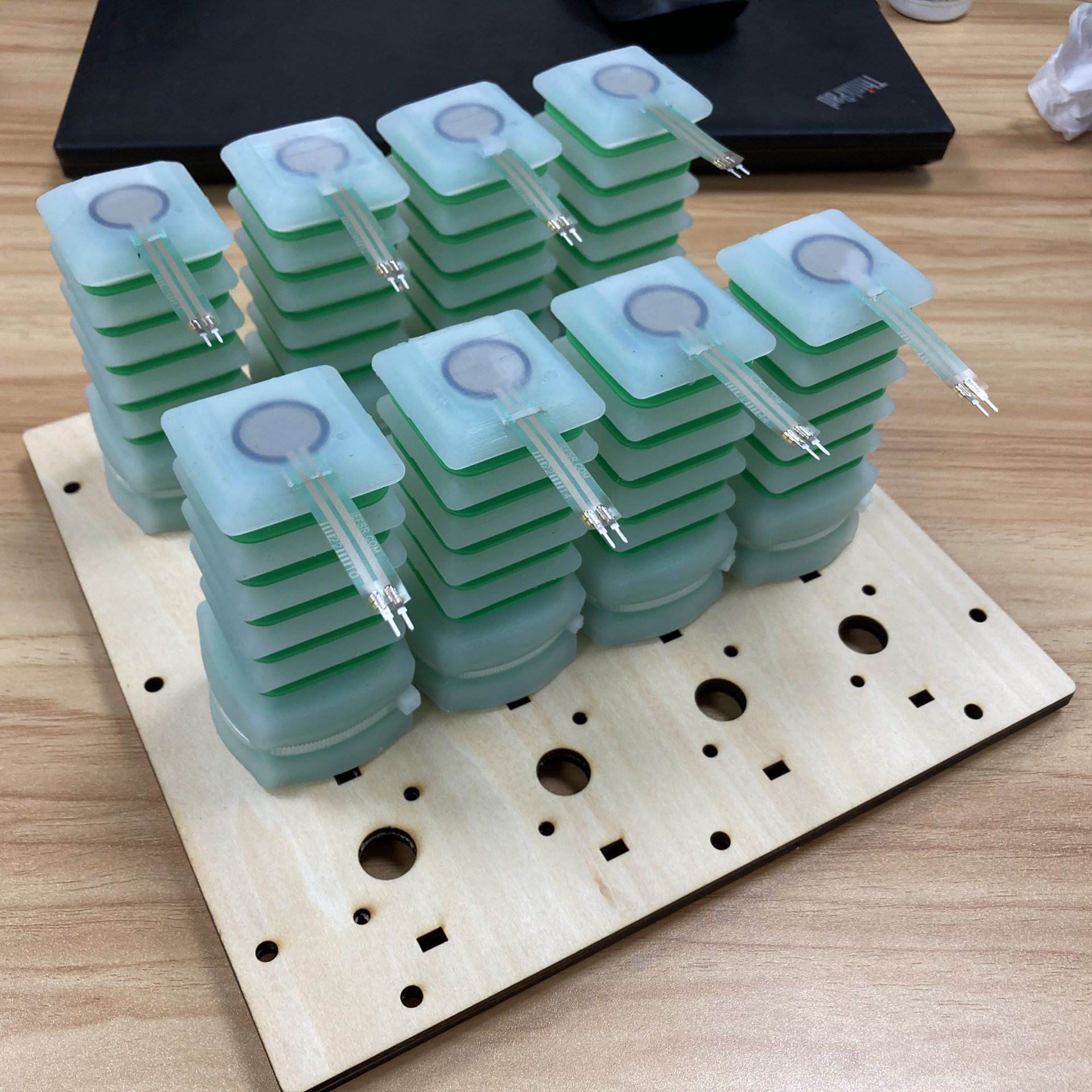
During surgical operations, the patient's position is often unstable, requiring constant manual attention. In order to increase precision and control of the patient, I created a soft, dynamic surface consisting of 16 custom silicone actuators able to individually extend and retract.
Force and air pressure sensors on each actuator, along with camera vision, allow for autonomous movements. The platform also works in conjunction with a robotic arm, demonstrating its capabilities of working in a system of surgical devices. This serves as a step toward more consistent and fully autonomous medical operations.
Research paper published in the 2025 IEEE 3rd International Conference on Sensors, Electronics and Computer Engineering (ICSECE 2025).
- TXSEF 2nd Place (2025)
- DRSEF 2nd Place (2025), 3rd Place (2024)
Custom silicone actuators
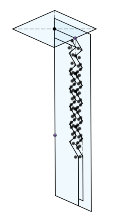
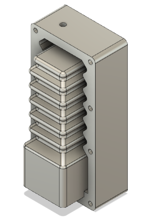
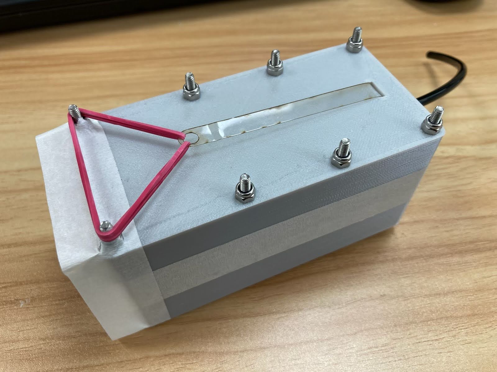
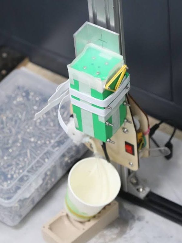
Creating the silicone actuators began in Fusion 360, creating sketches that defined its geometry. The mold was then designed by revolving this profile along different paths, ie. square or circular. After 3D printing the molds, they were assembled and injected with silicone 10A and tested.
Major improvements during iteration include optimizing the actuator geometry for greater range of motion and adding restriction rings to horizontally constrain movement.
Note: 3D prints are not air tight! During later testing I realized air was slowly leaking out of the actuators through the 3D printed adapters — a few layers of flex seal worked quite well.
Electronics
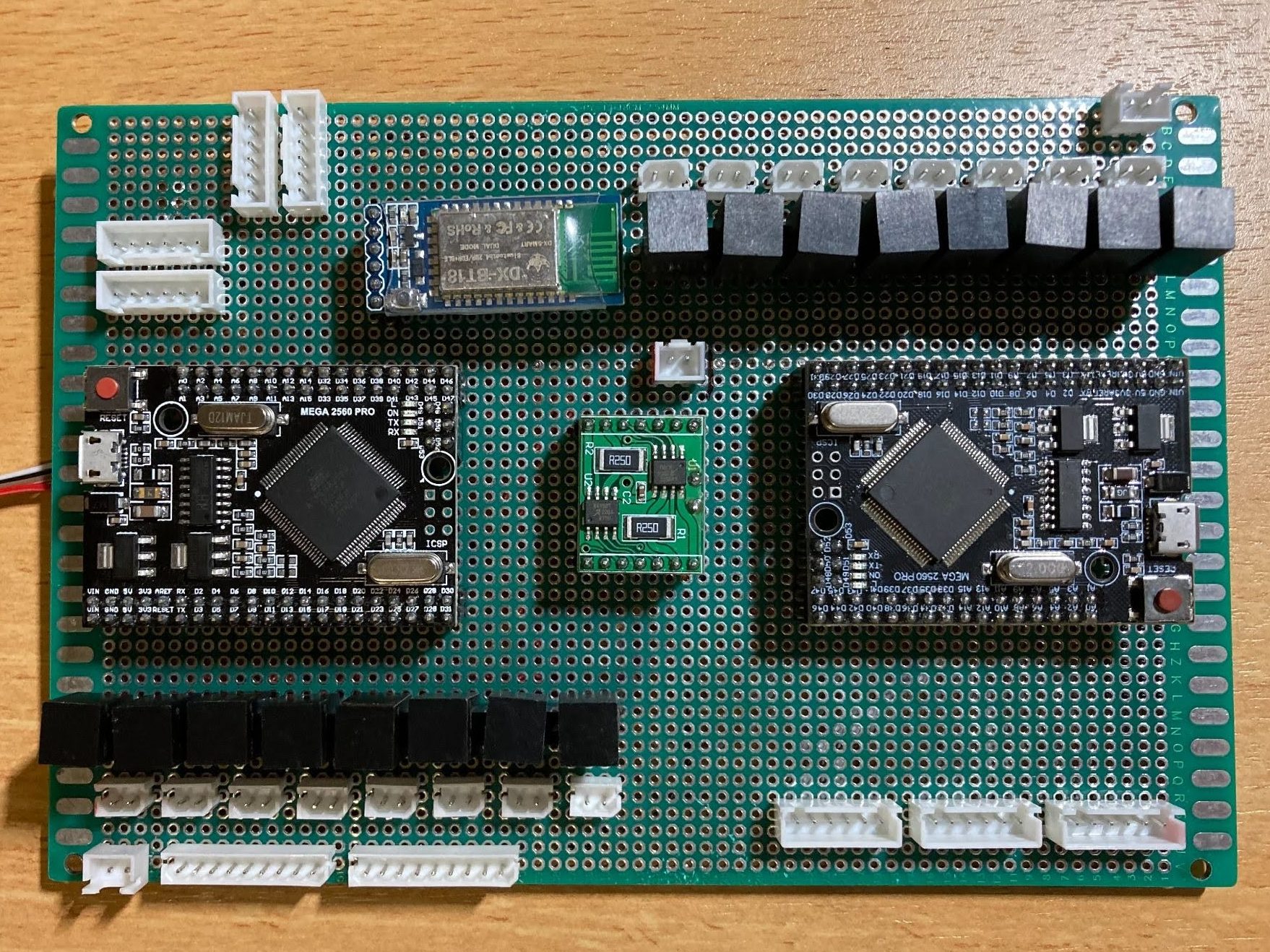
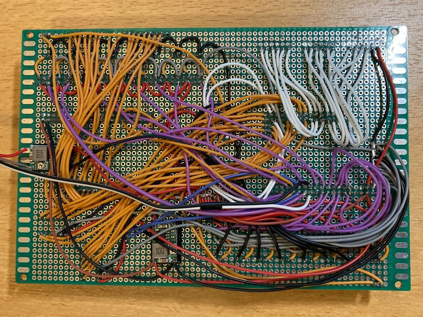
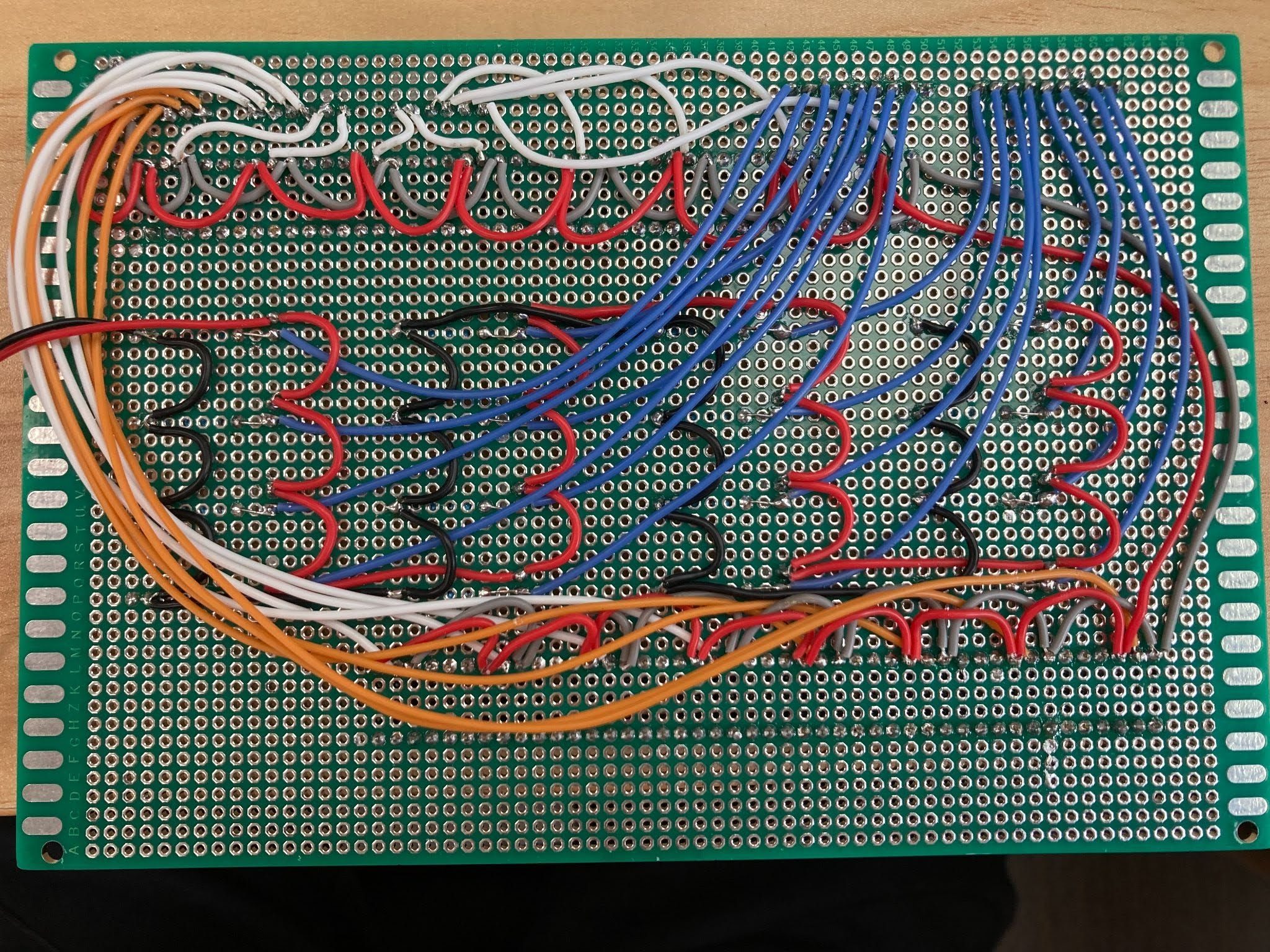
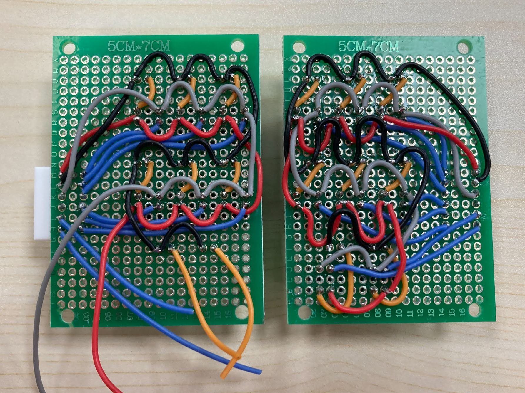
Everything is controlled by the main Arduino Mega, while a secondary Arduino Mega is used to supply more analog/digital pins. Communication between the Arduinos, K210 vision module, and robotic arm are facilitated through serial ports.
Components used
- 2 air pumps
- 32 valves
- 32 relays
- 16 force sensors
- 16 air pressure sensors
- Buck converter
- Bluetooth module
- 2 Arduino Megas
- K210 vision module
Everything was also hand-soldered, which, while it was a pain, made it easy to make adjustments on the fly and was a good way to gain experience.
Housing
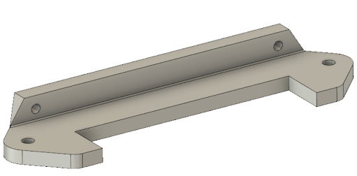
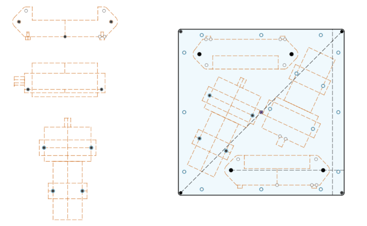
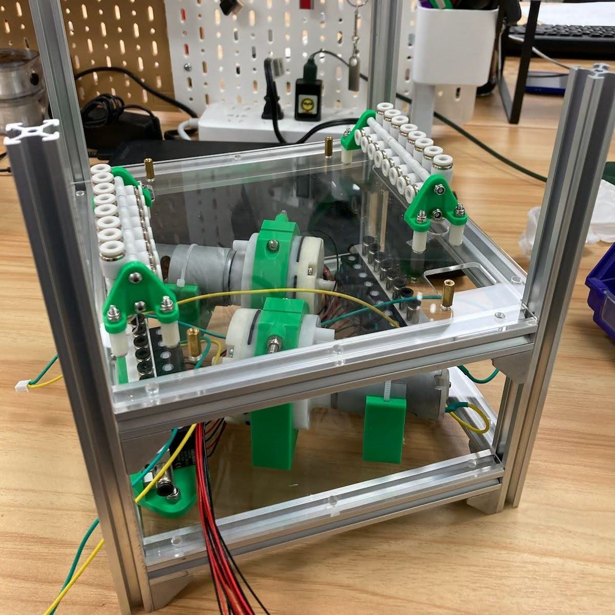
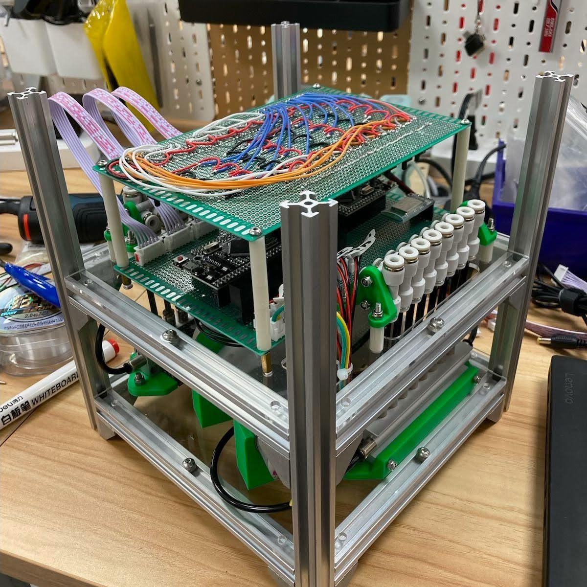
The structure of the housing consists of 15mm extrusions and metal corner brackets. I designed the layout of each level in Fusion 360 and laser cut them out of acrylic sheets. The top level uses two sheets of plywood for more strength, along with an extra extrusion across the middle. All mounts were custom designed and 3D printed.
The actuators are also modular — each mounted by two screws and connected only by the force sensor wire and pneumatic tube. This allows for different configurations and accounts for differently shaped actuators.
Programming
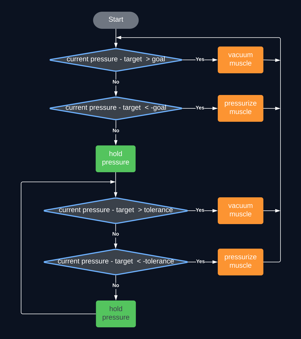
Controlling the actuators brought a major issue: oscillations. The simplest algorithm, bringing the air pressure to an exact value and holding it there, obviously failed as in reality, the pressure oscillated above and below the target pressure. The next progression was changing the target pressure to a target range, creating some tolerance. However, this too created oscillations as the pressure now simply bounced around the end of this range.
To truly solve this issue, I developed an algorithm specifically designed to prevent unwanted oscillations. Given a target air pressure, the actuator is vacuumed/pumped until it is within a goal range (eg. target ± 3). This pressure is then held within a tolerance range (eg. target ± 6). If the pressure exits the tolerance range, it is brought back into the goal range, thus preventing oscillations and creating a feedback loop.
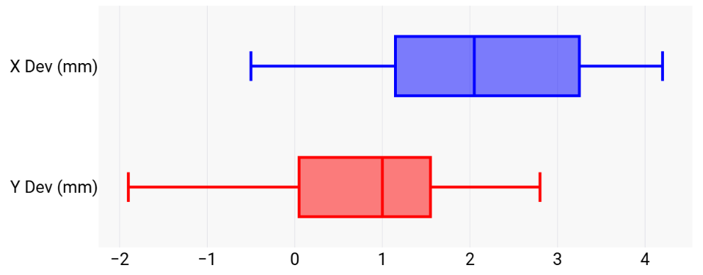
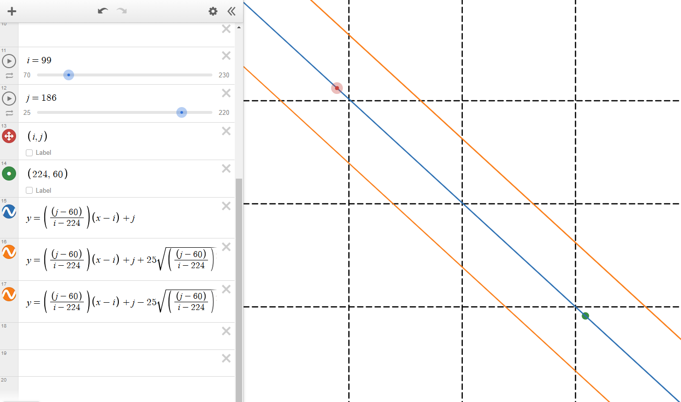
The K210 vision module (camera) mounted above the platform allowed for visual feedback. To convert pixel units from the camera to real life coordinates, the camera is mounted at a fixed, known height and data points were measured to find the relationship between pixels and millimeters in both the x and y axis. This served as an approximation to take into account camera distortion. With this data, regressions were performed as seen below.
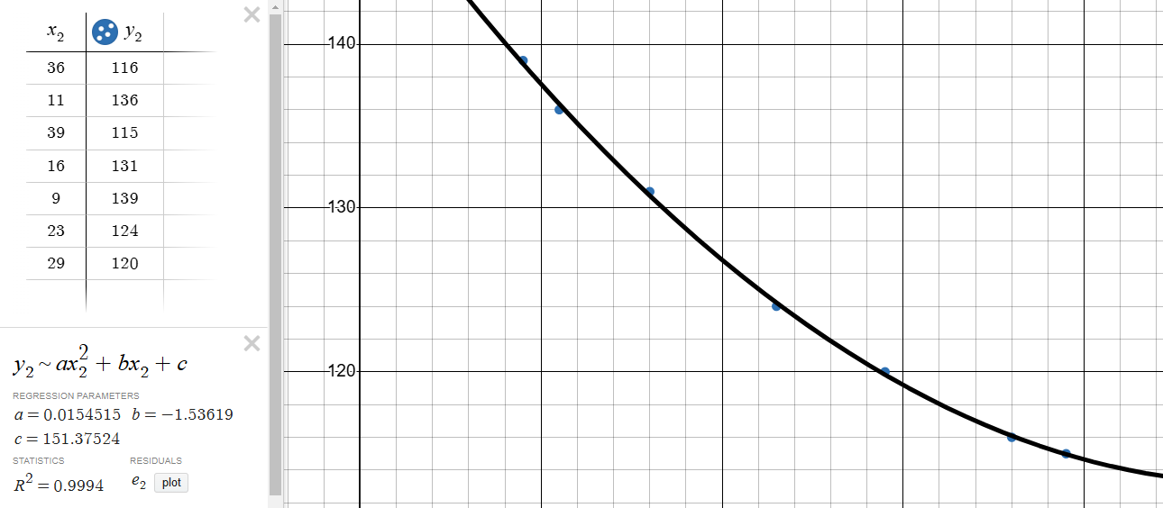
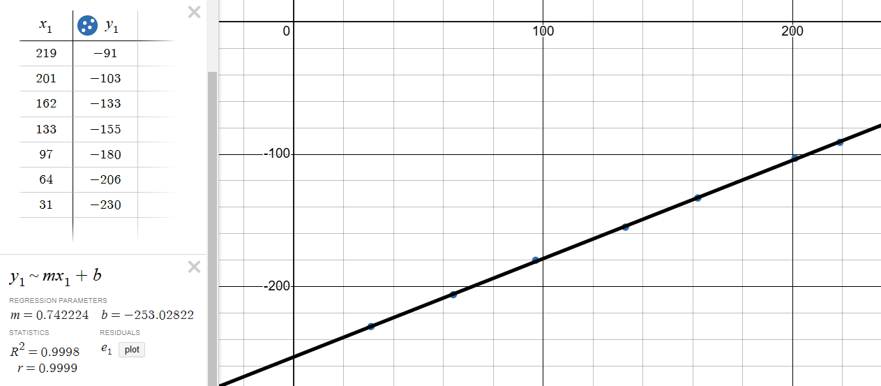
To control the 6DOF robotic arm, inverse kinematics were used. Given an x, y, z coordinate and tool angle, it calculates the angle that each servo needs to be at. In addition to this, it generates a straight line path between the current and target positions, incrementally sending coordinates along this path based on the given speed. Thus, the arm not only moves to the target position, but it does so in a predictable manner.
void moveToPos(float x, float y, float z, float phi, float speed) {

  float ang_6 = atan2(y, x);
  float hyp = -sqrt(pow(x, 2) + pow(y, 2));

  float wHyp = hyp - armLen[2] * cos(phi);
  float wz   = z   - armLen[2] * sin(phi);

  float delta = pow(wHyp, 2) + pow(wz, 2);
  float c4 = (delta - pow(armLen[0], 2) - pow(armLen[1], 2)) / (2 * armLen[0] * armLen[1]);
  float s4 = sqrt(1 - pow(c4, 2));
  float ang_4 = atan2(s4, c4);

  float s5 = ((armLen[0] + armLen[1] * c4) * wz   - armLen[1] * s4 * wHyp) / delta;
  float c5 = ((armLen[0] + armLen[1] * c4) * wHyp + armLen[1] * s4 * wz)   / delta;
  float ang_5 = atan2(s5, c5) - M_PI/2;
  float ang_3 = phi - ang_5 - ang_4 - M_PI/2;

  tarServPos[2] = round( 237.141 * ang_3 + 495);
  tarServPos[3] = round(-237.141 * ang_4 + 495);
  tarServPos[4] = round( 237.141 * ang_5 + 495);
  tarServPos[5] = round( 237.141 * ang_6 + 867.5);
  ...
Experimentation
Object manipulation
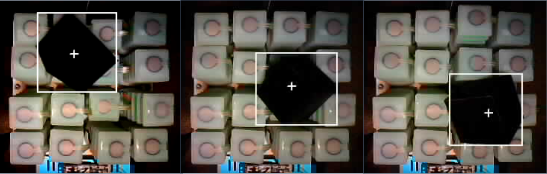
The first experiment is transporting a 50mm cube from a random location to the target location (bottom right corner). The camera tracks the cube through color detection, allowing a path to be generated between the cube's current and target position (shown below). Based on this path, the actuators conform to the cube's shape and guide it to the target location, before actively holding it in place.
Surgical stabilization
To simulate stabilizing a patient during medical scenarios and surgery, I used a silicone model hand. AprilTag detection allows for easy tracking and precise locational and angular data. Based on the hand's current position and angle, the actuators can once again conform to its shape and tilt it to reach the target angle.
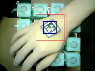
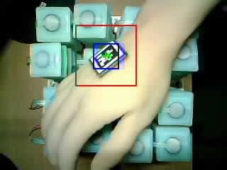
While the model hand is able to reach the target angle, it often shakes due to the flexible silicone actuators. This could be fixed in multiple ways: increasing the number of actuators in a given area, expanding the platform to better surround the hand, using stiffer silicone actuators, further constraining the actuators, or increasing actuator extension and retraction. So, while this prototype serves as a proof of concept, further development is needed in this area.
Robotic arm
To test the capabilities and precision of the robotic arm integrated into the system, it is tasked with moving a cotton ball. The camera detects the cotton ball, sending its coordinates to the Arduino which then controls the arm to pick it up.
The first experiment tests detection and consistency in picking up and transporting the cotton ball. The second experiment tests the accuracy and precision of the robotic arm (also simulating alcohol wiping in a medical context).