Deformation Tracking with Camera Motion
Research with UTD Mechanical Engineering Professor Dr. Dong Qian and his PhD students on analyzing excessive tissue deformation during surgical operations through digital image correlation and machine learning.
Journal publication coming soon!
Introduction
Digital Image Correlation (DIC) relies on a stable camera for accurate deformation measurement. This becomes problematic during situations where noise and movement are unavoidable, making DIC unreliable. In search of better solutions, the following research was conducted.
Two videos are taken of the same silicone deformation experiment: the moving video which includes random camera movement, and the fixed video which does not have camera movement, thus acting like the ground truth. These videos are rescaled to the same size and trimmed such that their starting frames match.
To analyze these videos, two approaches are tested: VoxelMorph and Lite-Tracker. With VoxelMorph, a custom CNN model is trained based on experimental and simulated data using Elastix as the ground truth. With Lite-Tracker, different homography and affine transformations are used to calculate and remove camera movement.
Methodology
VoxelMorph — generating data
To create simulated data for machine learning training, pyMAPDL was first used to generate 119mm x 55mm meshes from a given total displacement and number of steps. Next, random speckle patterns were generated and applied to each cell of the mesh. The speckle patterns were created by randomly assigning a shade to each cell before determining its cluster size (1–5 cells). To convert the meshes into images, PyVista was used to plot each mesh. The position of both the camera and the left side of each mesh were fixed before screenshotting and saving.
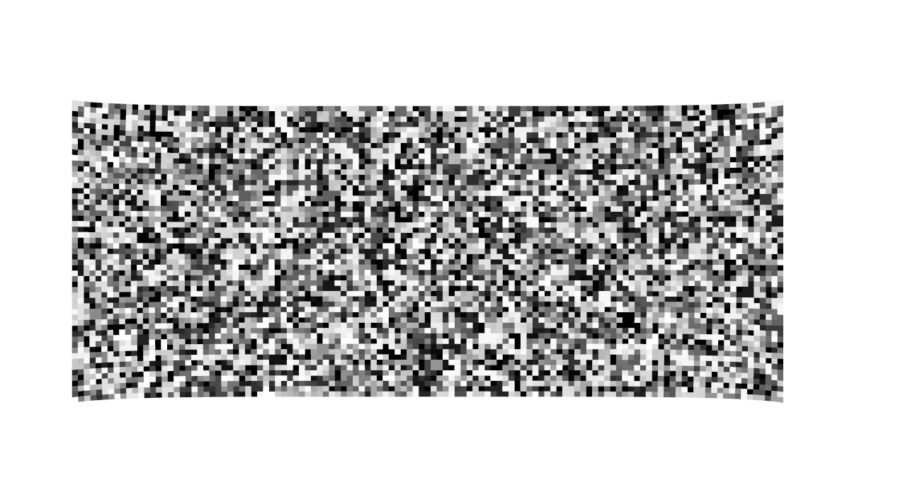
Elastix was then used on the fixed simulated and experimental data to generate the physical x and y deformation field between each image and output them as .npy. The training data sets were then created, each with two images and their corresponding ground truths. Both simulated and experimental (moving and fixed) data were used. To form the sets, the region of interest in each image was tracked to simplify and transform the ground truth as necessary.
VoxelMorph — machine learning
Using VoxelMorph and TensorFlow, a U-Net model was defined with the encoder features 16, 32, 32, 32, 32 and decoder features 32, 32, 32, 32, 16, along with a 2D convolutional layer at the end. It inputs two concatenated images, the moving and fixed, and outputs two identical copies of the x and y deformation fields allowing for the use of two losses, MSE and Grad l2 (weights 1 and 0.05).
When loading the data and preparing the data, geometric augmentation (affine and translate) is applied to both the images and deformation fields, while augmentation for appearance (brightness, contrast, and blur) is only applied to the images.
Lastly, early stopping is set to monitor the validation loss and stop training if the model stops learning, preventing overfitting and saving training time. Reducing the learning rate on plateau also aids in allowing the optimizer to make finer adjustments, helping the model converge smoother.
Lite-Tracker
In order to select and track the same points in both moving and fixed videos, the silicone piece ROI is manually selected. A homography is computed between a unit square (1 by 1 rectangle) and each ROI. This transformation is then used to map a 10 by 10 grid of points onto each ROI, ensuring that corresponding points align between the two videos. Along with this, 4 points on the clamp outside of the ROI are also selected in both videos. These are fixed points relative to the silicone piece and are later used to help remove camera movement. Using all of these points, Lite-Tracker with scaled_online weights is used to track each video. This gives a video output of the tracked points along with the pixel location of each point every frame.
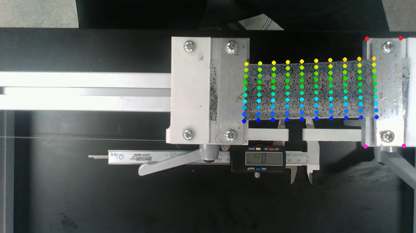
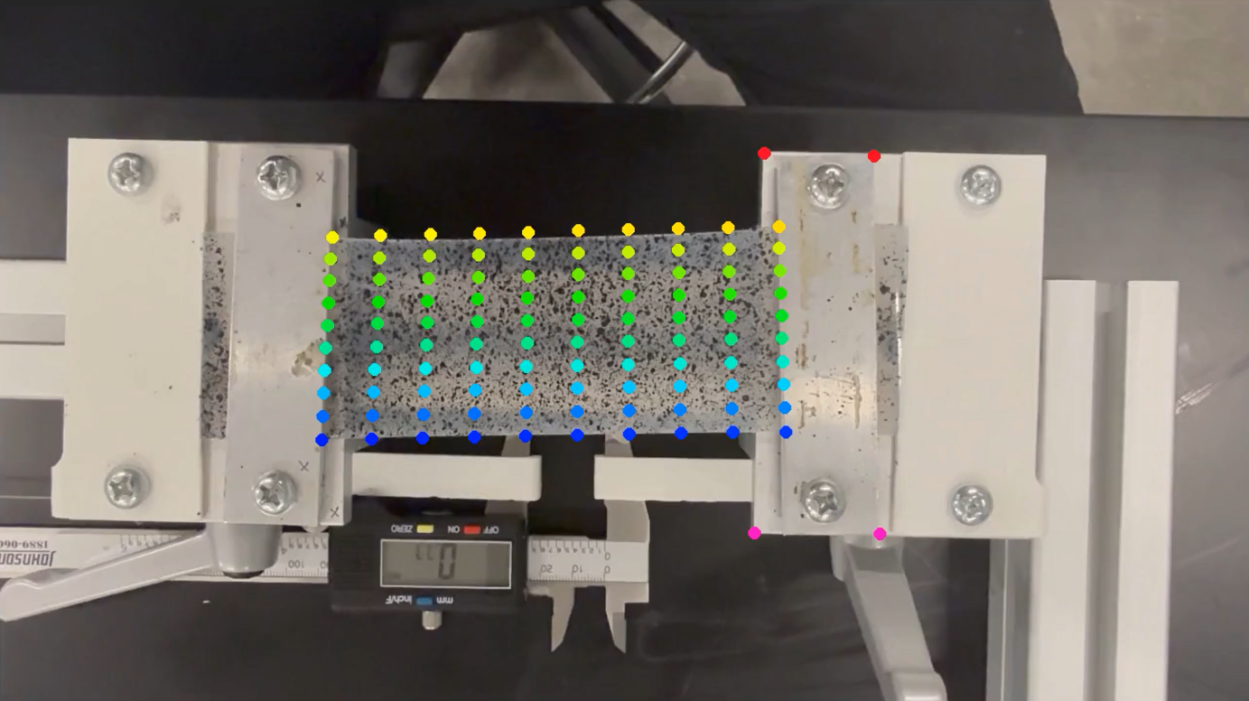
To remove camera movement from the moving video, the previous tracked points are first transformed by their respective homographies and then scaled to physical units. This moves all points onto a flat 2D plane, allowing for easier comparison to the ground truth.
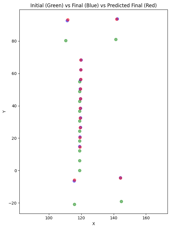
From the moving video, the four fixed points along with the 10 points on the right side of the ROI are used to calculate a 2D partial affine between their final and initial locations. As these points are fixed and do not deform, this affine transformation represents the total camera movement. Below is an example graph of these fixed points. Green shows their locations at the start of the experiment (initial), blue at the end of the experiment (final), and red shows the predicted final locations of the initial points based on the affine transformation. The inverse of this is then applied to all points, thus removing camera movement from the moving video. In both videos, the total deformation is calculated by subtracting the initial locations from the final locations, and the results are then compared.
Results
VoxelMorph
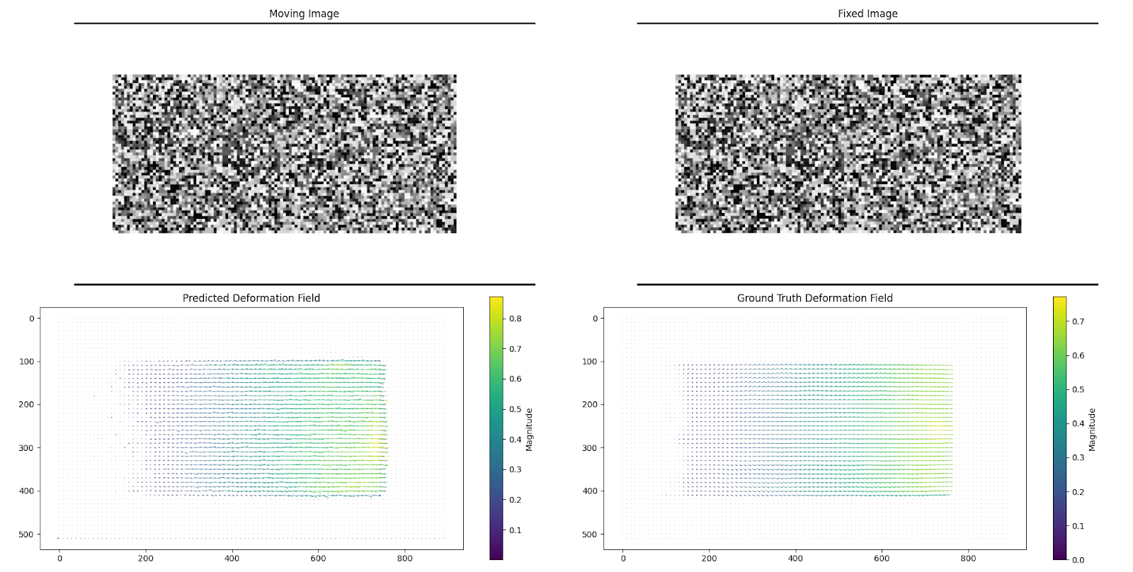
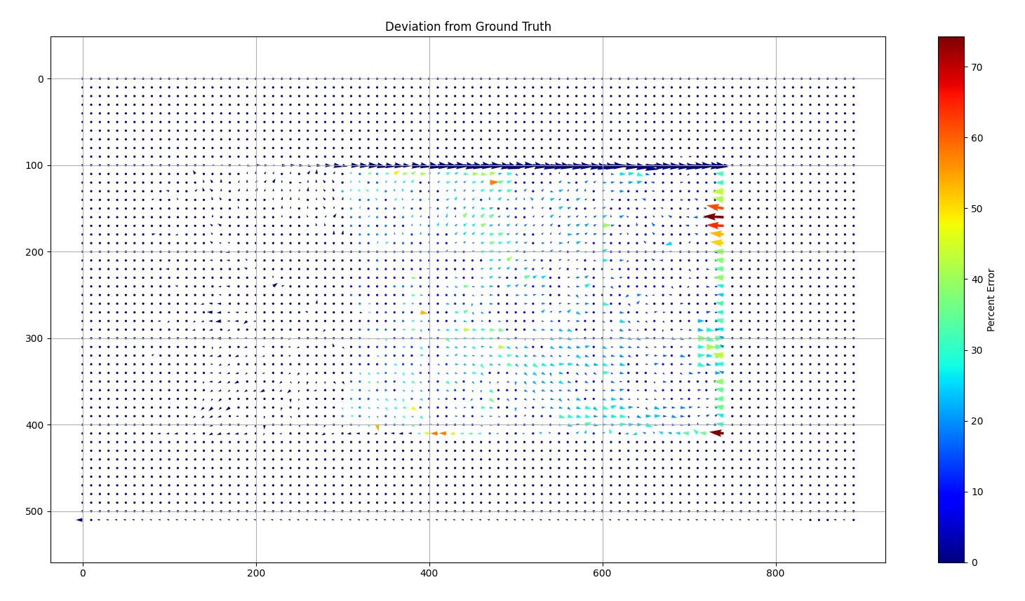
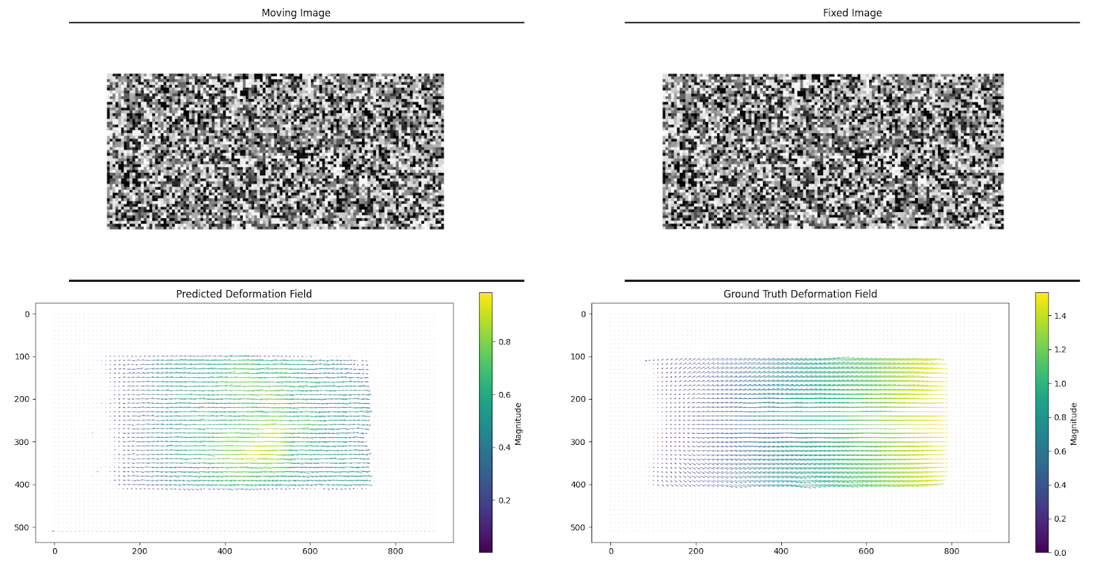
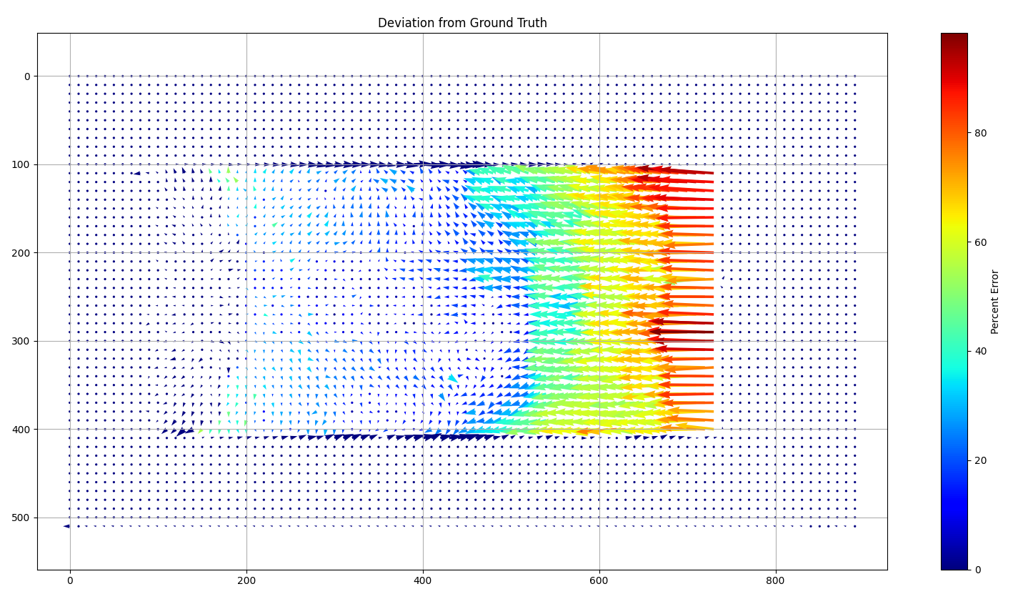
Simulated 0.7mm step deformation — mean percent error: 15.17%
Simulated 1mm step deformation — mean percent error: 17.45%
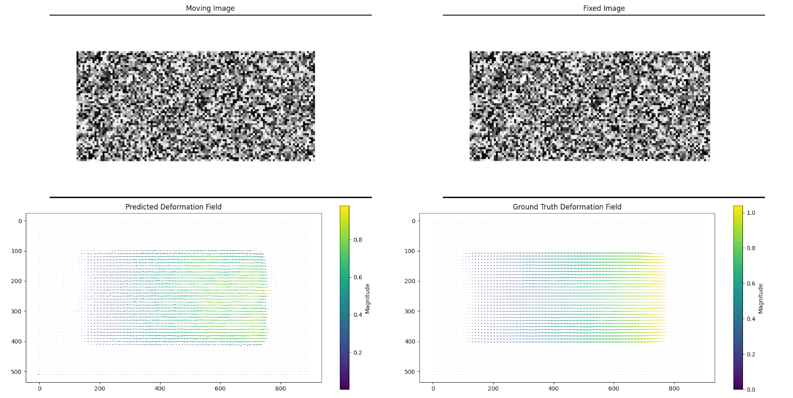
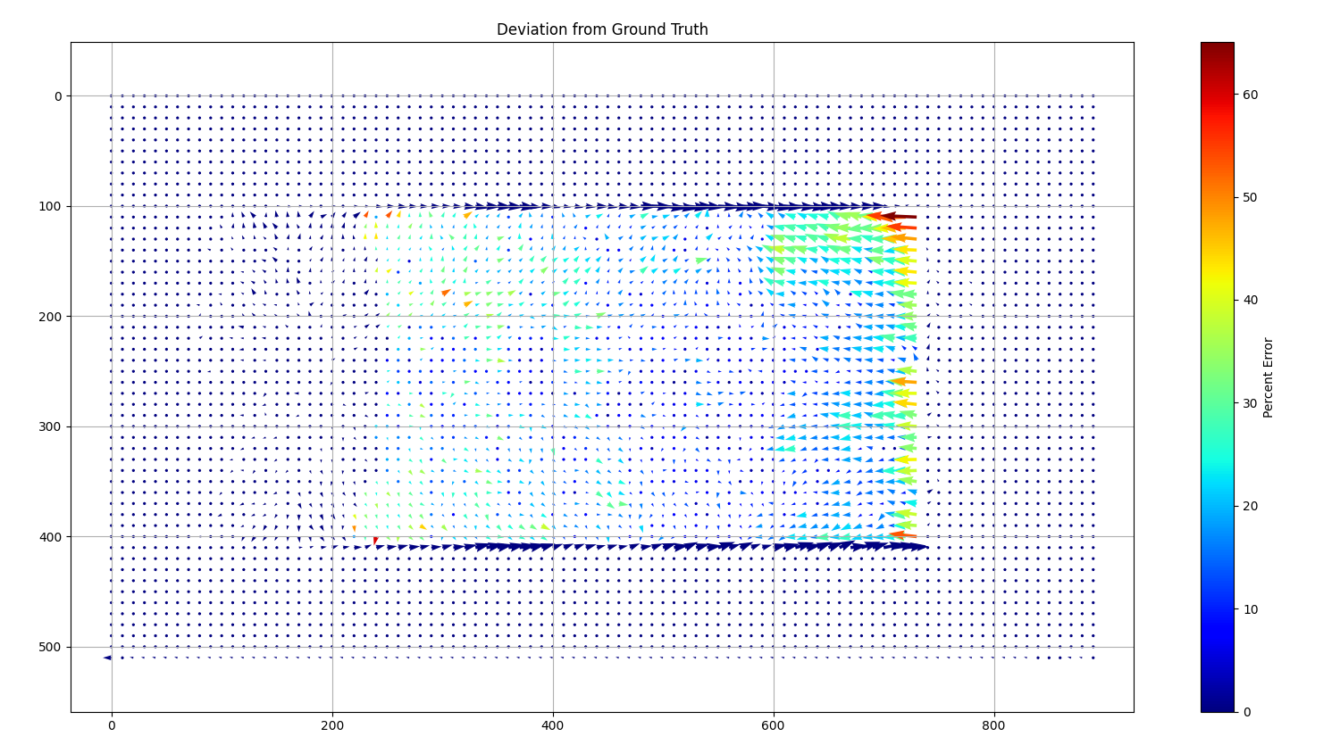
From these results, it can be seen that the deformations near the edges of the ROI vary from the ground truth. This could be attributed to the fact that around the edges of the experimental training data, Elastix would detect the table around the ROI as it stretched, creating errors in its calculations. This was most likely reflected in the overall model, as seen in the predictions of the simulated data.
This model was also only trained on smaller deformations, up to 1mm. When trying to predict larger deformations such as 1.5mm, the model fails and underpredicts.
Simulated 1.5mm deformation — mean percent error: 35.15%
Lite-Tracker
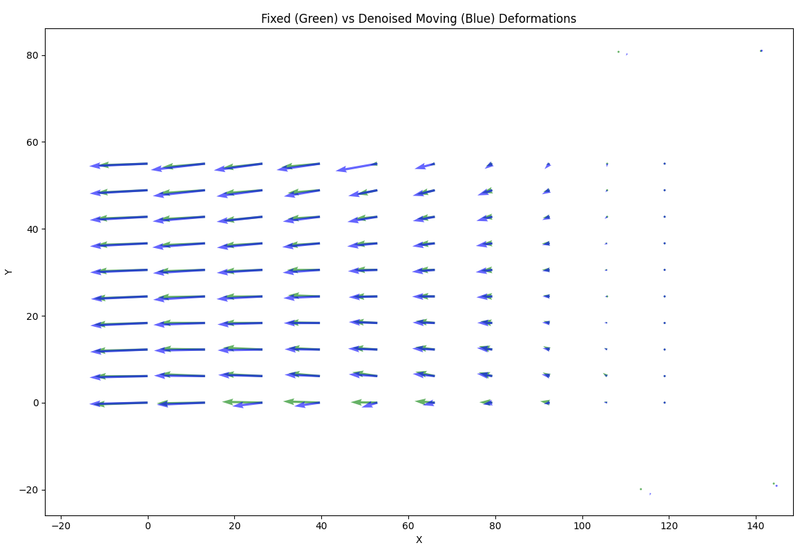
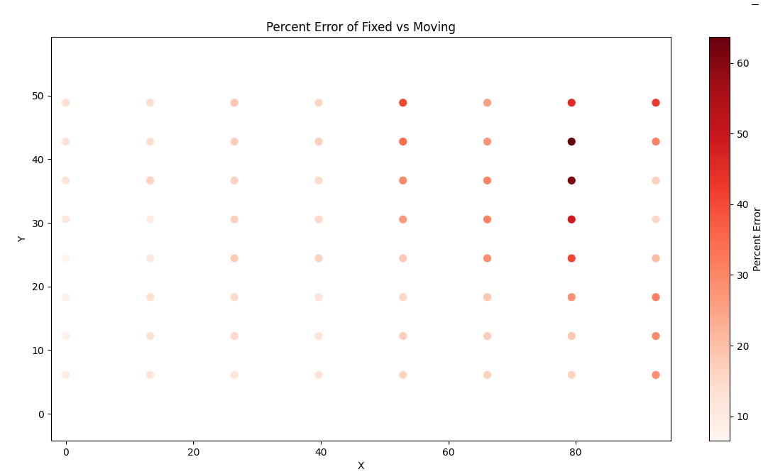
It can be seen that the four fixed points between the fixed and moving videos do not precisely match. This could potentially be due to issues with manual selection or differences in height compared to the ROI, causing the homography to be slightly inaccurate. Removing the homography or adding a second affine transformation better matched these four points but led to more inaccurate results.
Ignoring the top and bottom row of points (as they stray off the silicone piece), a mean percent error of 21.33% was obtained.